- 电话: 0086 13501592453
- 电子邮件: sales@consnant.com

交流输入:MCB 63A/3P*1、UK35*1
光伏输入:MCB 25A/2P*6、DC-SPD*6
电池接入:MCB 125A/1P*3
主负载断开:MCB 125A/1P*3、63A/1P*3
主负载断开由 400A 接触器(常闭)控制
配置:交流C类3+1方式20KA/40KA防雷器*1,直流输出防雷:C类直流防雷器*1
应用领域:
电信;
数据中心
编号 :
TRSS-48300订单(起订量) :
1 pcs支付 :
T/T产品产地 :
China颜色 :
Black装运港 :
Shenzhen交货时间 :
1-2 weeks重量 :
37 Kg48V 300A 嵌入式电信电源系统
描述
TRSS-48300嵌入式电源 是公司根据多年开发和在线运行经验设计的新一代高可靠、高性能混合能源系统。系统配置支持1-6个热插拔整流模块和1-6个光伏模块。系统监控模块具有电池管理功能和供电系统监控功能。适当配置传感器可以实现环境监测,并提供多组备用监测量。可提供RS485通讯接口,方便远程监控和无人值守操作。
这种嵌入式电源主要用于户外机柜。
主要产品规格
|
|
输入电压范围 |
输出电压 |
输出(最大) |
输出最大功率 |
配置数量 |
|
|
整流器 模块 |
176~300Vac |
-53.5V直流 |
300A |
18千瓦 |
6 |
|
|
太阳能充电控制器模块 |
120~425V直流 |
-54.5V直流 |
300A |
18千瓦 |
6 |
|
|
配置 |
||||||
|
交流输入:MCB 63A/3P*1、UK35*1 光伏输入:MCB 25A/2P*6、DC-SPD*6 电池接入:MCB 125A/1P*3 主负载断开:MCB 125A/1P*3、63A/1P*3 主负载断开由 400A 接触器(常闭)控制 |
具体配置:可根据客户定制
|
|||||
|
配置:交流C类3+1方式20KA/40KA防雷器*1,直流输出防雷:C类直流防雷器*1 |
||||||
原理介绍
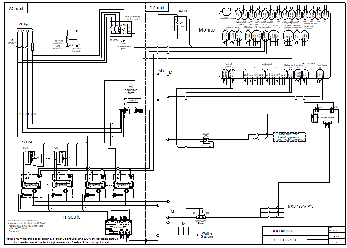
TRSS-48300嵌入式供电系统原理如下:

系统由三相交流市电通过交流输入断路器供电,一路给整流模块供电;同时,三相样本送至监控板进行交流电压检测。整流模块的输出合并后,负极分为两路。第一路分别通过直流接触器和断路器输出到直流负载负输入端,第二路通过主分流器和断路器连接到电池负输入端;直流接触器在监控控制下保护电池免于过放;整流模块的输出正极连接负载正极,电池正极连接输出正极排。
环境条件
|
环境参数 |
运行环境条件 |
运输环境条件 |
储存环境条件 |
评论 |
||
|
项目 |
范围 |
|||||
|
气候条件 |
温度 |
低温 |
-40℃ |
-40℃ |
-45℃ |
-40℃满载启动,+45~+75℃线性下降 |
|
高温 |
45℃ |
70℃ |
70℃ |
|||
|
湿度 |
相对湿度低 |
5% |
/ |
5% |
/
|
|
|
相对湿度高 |
95% |
/ |
95% |
|||
|
缩合 |
没有 |
/ |
没有 |
|||
|
高度 |
4000米 |
4000米 |
|
3000~4000m减容产出 |
||
|
机械应力条件 |
颤动 |
正弦振动: 5~9Hz:振幅3.5mm; 9~200Hz:加速度10m/s2; 3 轴向,扫频 每个方向 5 次振动 |
2~10Hz:30m2/s3; 10~200Hz:3m2/s3; 200~500Hz:1m2/s3; 3 轴向,每个方向 30 分钟 |
/ |
仅限插框,测试时取出整流模块和监控模块 |
|
|
冲击(碰撞) |
加速度250m/s2; 脉冲宽度:6ms; 3轴6次每次碰撞500次 |
加速度400m/s2; 脉冲宽度:6ms; 3轴6次每次碰撞500次 |
/ |
|||
|
降低 |
/ |
跌落高度1m;底面1次 |
/ |
|||
|
冷却方式 |
模块强制风冷 |
风从前面进来,从后面出去 |
||||
系统结构及布局图:

技术参数
1.输入特性 | ||||
在。 | 项目 | 技术参数 | 评论 | |
1.1 | 交流输入额定电压 | 单相220Vac/三相380Vac |
| |
1.2 | 交流输入电压范围 | 176Vdc~300Vac | 工作繁忙 | |
1.3 | 交流输入最大电流 | 40A | 1相,最多供电:2个模块 | |
1.4 | 交流输入电压频率 | 45~65Hz(典型值50/60Hz) |
| |
1.5 | 交流功率因数 | ≥0.99 | 220 Vac额定负载 | |
1.6 | 光伏组件输入 | 120Vdc~425Vdc(启动电压160Vdc以上) |
| |
1.7 | Pv-额定输入电压 | 340伏直流 |
| |
1.8 | MPPT电压范围 | 120Vdc至340Vdc |
| |
1.9 | 光伏组件最大输入电流 | 17A |
| |
1.10 | 光伏组件反极保护 | 输入极性错误,无损坏 |
| |
1.11 | 光伏组件输入保险 | 正保险和负保险 |
| |
1.12 | 光伏最大输入电压 | 450Vdc(电源不可损坏) |
| |
2.输出特性 | ||||
项目 | 技术参数 | 评论 | ||
2.1 | 整流器输出电压范围 | -43.2Vdc~-57.6Vdc(典型值-53.5Vdc) |
| |
2.2 | 整流器输出最大功率 | 18千瓦 |
| |
2.3 | 光伏输出电压范围 | -42Vdc~-58Vdc(典型值-54.5Vdc) |
| |
2.4 | 稳压精度 | ≤±1% |
| |
2.5 | 输出纹波和噪声 | ≤200mVp-p | 额定输入电压和负载以及带宽限制为 20 MHz | |
2.6 | 均流不平衡 | ≤±5% | 在50- -100%负载范围内 | |
2.7 | 整流模块效率 | ≥93% | 220 Vac / 额定负载 | |
2.8 | 光伏组件效率 | ≥95% | @340/40%~70%负载 -54.5Vdc | |
2.9 | 启动时间 | 3~10秒 | 额定输入电压启动至输出电压建立到设定值,启动输出需使用预流限制功能 | |
2.10 | 开/关过冲幅度 | ≤±5% | 当任一模块热插拔时(负载电流不应大于工作模块的总输出电流),系统输出电压波动 | |
2.11 | 动态响应 | 过冲范围 | ≤±5% | 25% -50% -25% 或 50% -75% -50% 负载变化 |
恢复时间 | ≤200µS | |||
2.12 | 温度系数 | ≤±0.02%/℃ |
| |
2.13 | 声压计加权噪声电压 | ≤2毫伏 |
| |
2.14 | 宽带噪声电压 | 3.4~150KHz | ≤50毫伏 |
|
0.15~30兆赫 | ≤20毫伏 |
| ||
2.15 | 离散噪声电压 | 3.4~150KHz | ≤5毫伏 |
|
15~200KHz | ≤3毫伏 |
| ||
20~500千赫 | ≤2毫伏 |
| ||
0.5~30兆赫 | ≤1毫伏 |
| ||
2.16 | 电压降 | ≤500毫伏 |
| |
在。 | 项目 | 技术参数 | 评论 | |
3.1 | 交流输入过压保护 | 300伏直流电 | 可自恢复,相差不小于10Vac | |
3.2 | 光伏输入过压保护 | 430伏直流 | 可自恢复,差值不小于15Vac | |
3.3 | 交流输入欠压保护 | 85伏直流电 | 可自恢复,回差不小于5 Vac | |
3.4 | 光伏输入欠压保护 | 110伏直流电 | 可自恢复,差值不小于40Vac | |
3.5 | 整流器输出过压保护 | -59Vdc~-61Vdc | 锁定,无法恢复,需要重启 | |
3.6 | 光伏输出过压保护 | 内部-58.5至-60.5Vdc,外部:63Vdc | 锁定,无法恢复,需要重启 | |
3.7 | 输出欠压保护 | 电池断电保护 | 通过监控,可以实现电池断电,并可设置保护点 | |
3.8 | 输出限制保护 | 有 |
| |
3.9 | 输出短路保护 | 有 | 长期短路,可自行恢复 | |
3.10 | 过温保护 | 环境温度75℃时可自动恢复 |
| |
3.11 | 电池极性接反保护 | 没有 | 根据用户需要可具有电池极性反接保护功能 | |
3.12 | 光伏功率不足保护 | 输入功率 <50W关机5分钟 | 当输入电压大于 160 Vdc 并持续 5 分钟时,模块启动。 | |